This project started when I noticed that my garage door wall button didn't light up. The button worked fine, but that little LED that illuminates the button was broken. I went on Amazon to get a replacement, and found that simple buttons with LED's were pretty pricy. (I expected them to be < $5). If I was going to spend $10 on a lighted button, I wanted something better. That's how it started, but obviously I took things way further.
I found a big button like this from Adafruit. This button is big enough to hit with you elbow on the way in and durable enough (theoretically arcade rated) to last.
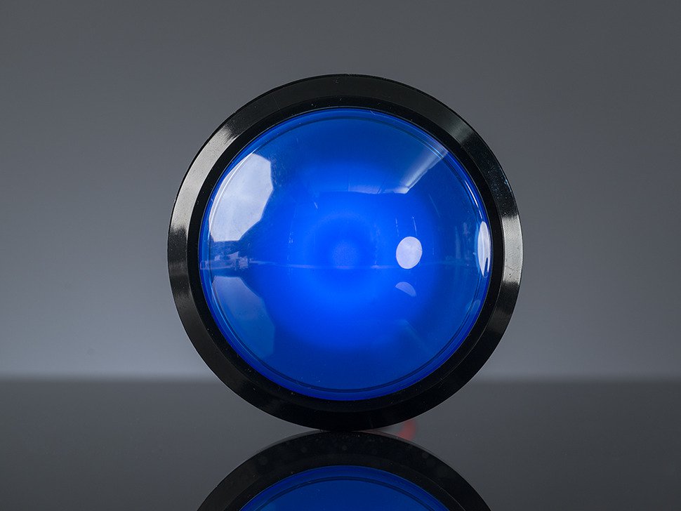
After ordering this button, I did some research to figure out how bright I could make the LED. As with most research, I went down the rabbit hole.
Garage Door Wall Controls
Garage door wall controllers have 4 functions as far as I can tell:
- Open/Close- Opens and closes the door.
- LED Illumination- Lights the button.
- Lock- Prevents the door from moving.
- Light- Triggers the lights to come on for some interval.
Here's the schematic I came up with for how all of that works: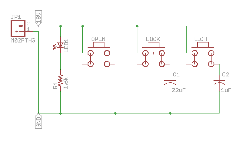
- LED Function- Based on 18.5V on my system and a 1.6K resistor, I'm estimating I can use 10mA to run an LED. Pretty dim. The more current you pull, the more you may trigger an open/close event. The manufacturer says that you can't use two lit buttons, which means that at 20mA you may loose function.
- Open/Close Function- This happens by just shorting the two wires, or grounding the 18V line.
- Lock Function- Apparently this happens when you momentarily introduce a 22uF capacitor across the two lines. I'm not sure how you can tell if it's locked/unlocked.
- Light- Apparently this happens when you momentairly introduce a 1uF capacitor across the line.
Switch and LED
The massive switch is trivial to implement. Connect the two wires to the COM and NO (Common and Normally Open) terminals of the switch. The door will open and close. Simple.
The LED is a little bit trickier. According to my research, I can use 10mA to power that LED. The first step is to figure out how much current the LED draws with it's built-in resistor. When it comes I'll do that.